Intro
The next step was to develop a functional version of the system, following the design developed during the first paper prototyping phase (see the article Concept and Low-Fi Prototyping).
The device was imagined as a lantern-shaped object containing LED lights capable of changing color according to the moisture level of the soil.
Hardware Component
The prototype was built using the following components:
- Arduino R4 Wi-fi Board
- Soil moisture sensor
- Modulino Pixels LED module
- Power supply
- Wi-Fi network connection
Circuit Setup
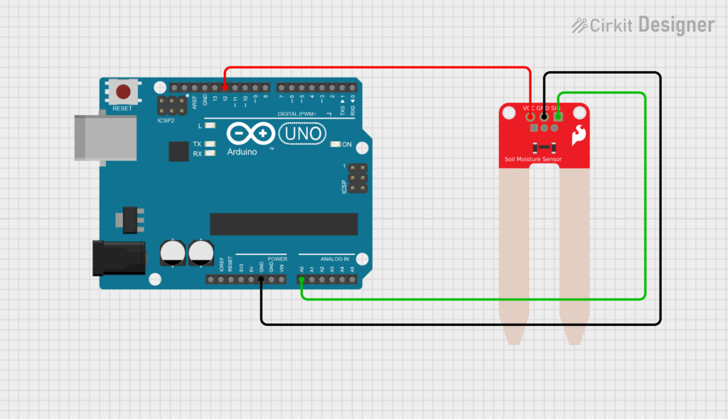
Figure 1. Circuit setup for the soil moisture sensor.
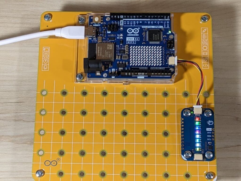
Figure 2. Circuit setup for the Modulino Pixels module.
The soil moisture sensor (Fig. 1) is connected to:
- Analog pin A0 for reading the sensor value.
- Digital pin 12 for powering the sensor.
The sensor is powered only when a measurement is taken. This prevents it from being continuously powered, which could accelerate electrode corrosion and reduce the sensor’s lifespan. It also helps reduce power consumption. In addition, The Modulino Pixels module (Fig. 2) is connected directly to the Arduino board
Code Structure
Soil Moisture Measurement
The soil moisture sensor monitors the condition of the soil: Every sampling cycle, the system activates the sensor, waits a short time for the signal to stabilize, reads the analog value, and then immediately turns the sensor off.
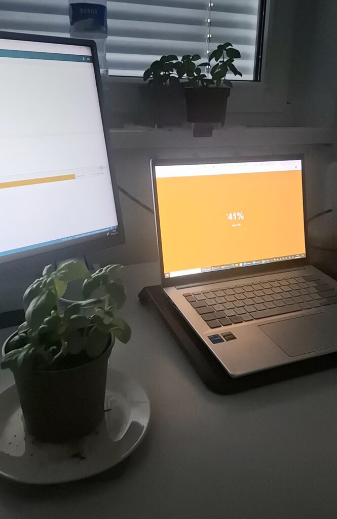
The measured value is converted into a moisture percentage using calibration values obtained during testing. In this prototype, a value of 0 corresponds to dry soil, while a value of 685 corresponds to wet soil. The result is then mapped to a percentage between 0% and 100%, making the data easier to interpret and use for the visual feedback system
Figure 3. Real-time soil moisture reading displayed through the web interface, showing the current humidity percentage and sensor value
LED visualisation
After each measurement, the LEDs change gradually as the moisture percentage increases. When the soil is very dry, the LEDs appear red. As the moisture level rises, the colour progressively shifts through orange and yellow tones, eventually becoming green when the soil is sufficiently wet.
Video 1. LED feedback system setup
Wi-Fi Connection
The device connects to a local Wi-Fi network using the WiFiS3 library. Once connected, it starts a web server and creates a local address using mDNS. This allows users to access the device through a web browser by typing:
http://light-plant.local
without needing to know the device’s IP address.
Digital Interface
A responsive web application was designed to monitor and manage multiple plants. The home screen highlights the plant connected to the moisture sensor, displaying its soil moisture level together with its care requirements, including watering, light exposure, and fertilization. The app also contain an overview of all the connected plants, organized by indoor and outdoor categories, allows users to quickly monitor their status and access more detailed information.
UI Design – Design System
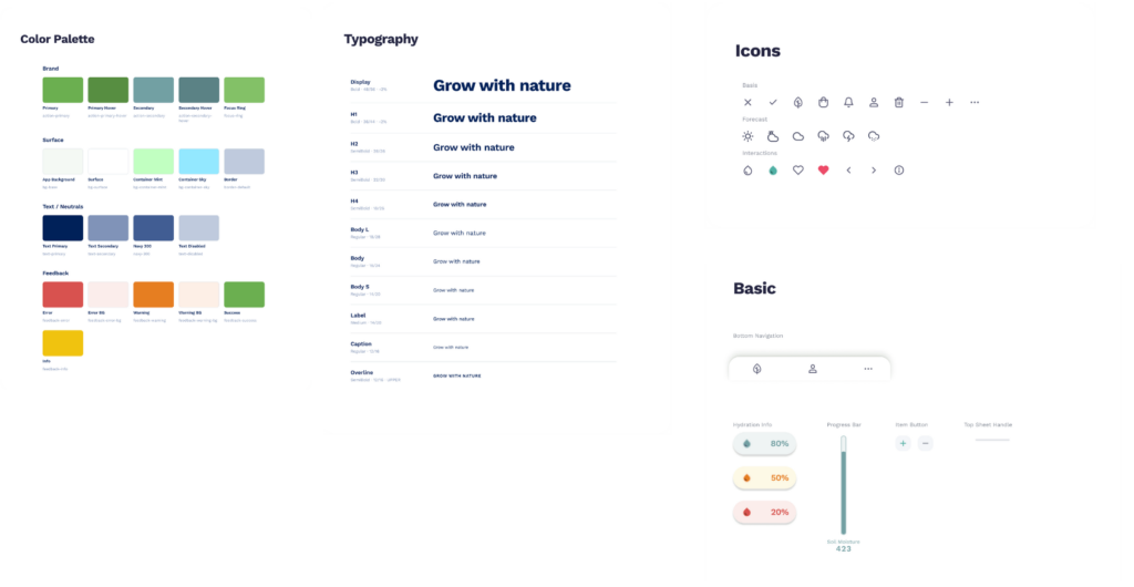
Figure 4. Design system for the digital Interface inlcuding: color palette, typography, icons and basic components
UI Design – Mobile and Desktop Application
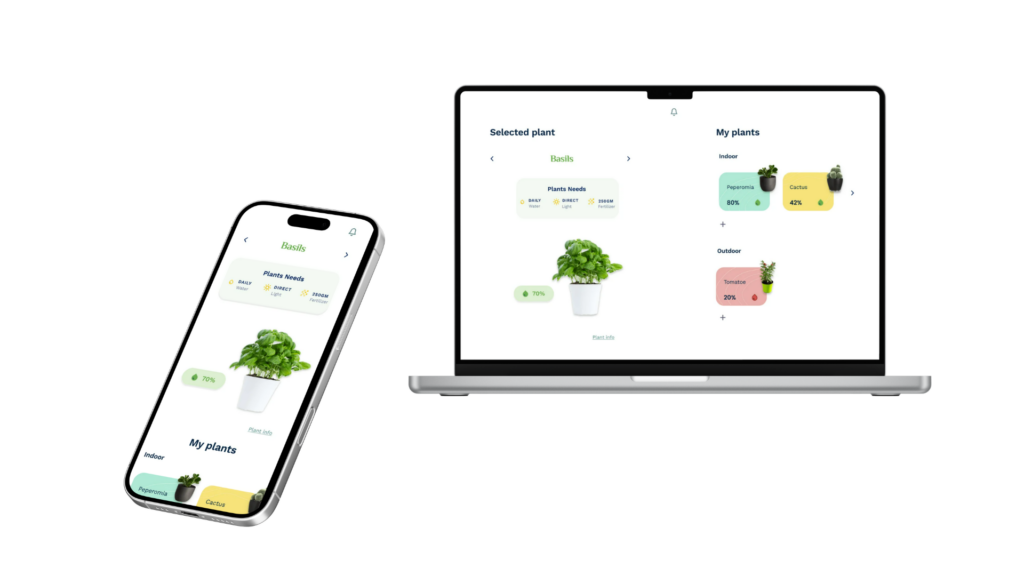
Figure 5. Mockups for Mobile and Desktop
